Gap Draught - Beer Lines Monitoring System
Summary
This product is connected to draught beer lines at bars and pubs. It monitors the temperature, volume and TDS of the beer.
The system is used by the bar owner to ensure that the bartender is pouring the correct amount of beer and not giving away free
beers to their friends (Gap Draught integrates with Point of Sales software to link a pour with a transaction).
The system is also used by breweries to see how much of their beer is being used at the bar, how much glassware they should have available and whether the beer is being served correctly.
My role in this project was to design and implement the hardware and firmware for the system.
The gateway device is the centre of the system and is responsible for collecting data from the nodes and sending it to the cloud via MQTT.
The node devices are responsible for collecting the pour data from the tap sensors and sending it to the gateway when requested.
Beer line coolers (often situated near the taps) can also be monitored by attaching a
temperature probe to a port on the node device.
This flexible and extendable topology was chosen as Gap Draught is targeting the United Kingdom where bars can have in excess of 60 taps and having a
gateway-like device at every tap set would become costly.
The product will also be sold to bars in South Africa, meaning that battery back-up
was a must as power outages can cause significant downtime. The gateway houses up to
three 18650 lithium cells which provide ample power for the device to survive the outages.
The number of batteries inserted can be varied depending on the number of nodes attached to the
gateway. Removable 18650 cells were chosen as exporting products with included lithium cells is
very expensive; by inserting them on arrival in the UK, the cost is significantly reduced.
TDS is sensed by measuring the conductivity of the liquid passing through
the tap sensor. This allows you to determine whether the beer lines have
undergone a cleaning cycle (cleaning solution is significantly more
conductive than beer, which is in turn quite a bit more conductive than water).
When beer lines are left for too long, yeast can build up and cause the beer to
taste bad. This cleaning cycle needs to be done approximately once a month.
By detecting cleaning cycles, the bar owner and breweries can ensure that their
beer is always tasting fresh.

The Gap Draught system diagram.
Hardware
Gateway
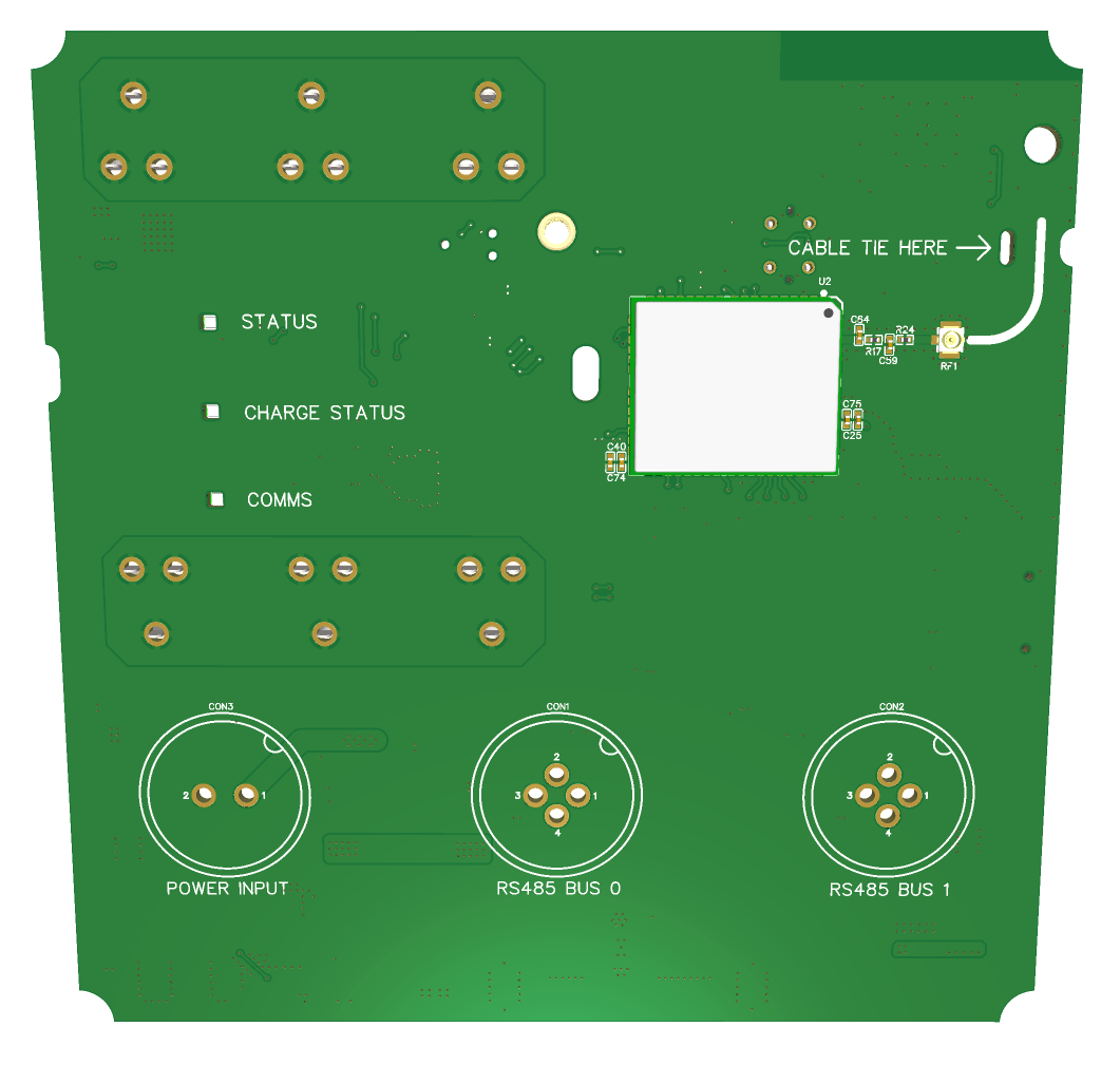
On the back of the gateway's PCB we have the following components:
- An STM32G0 microcontroller.
- A CR2032 coin cell holder to power the STM32's RTC when the primary batteries are discharged.
- Three positions for 18650 lithium cells.
- Li-Ion protection circuitry (prevent over-discharge and over-current from damaging the cells).
- A nano SIM card holder.
- Two RS485 driver ICs and a TVS diode pair for ESD protection.
- Rear-firing LEDs to indicate the state of the gateway, charge and communication.
- A 2A switching lithium-ion charger circuit.
- A boost mode SMPS to convert the batteries' nominal 3.6V to the 18V for the buses.
- A buck-boost mode SMPS to convert the batteries' output to 3.8V for the Quectel 4G LTE modem (see the front PCB below).
- Bulk decoupling capacitors for the modem (which is placed on the other side).
- A buck mode SMPS to convert the 18V bus voltage to 5V for the RS485 driver ICs.
- Switch over circuitry to switch between the main input power and the batteries should there be a loss of power.
- An ESP32-C3 WiFi modem (not currently used).
The gateway's PCB - back.
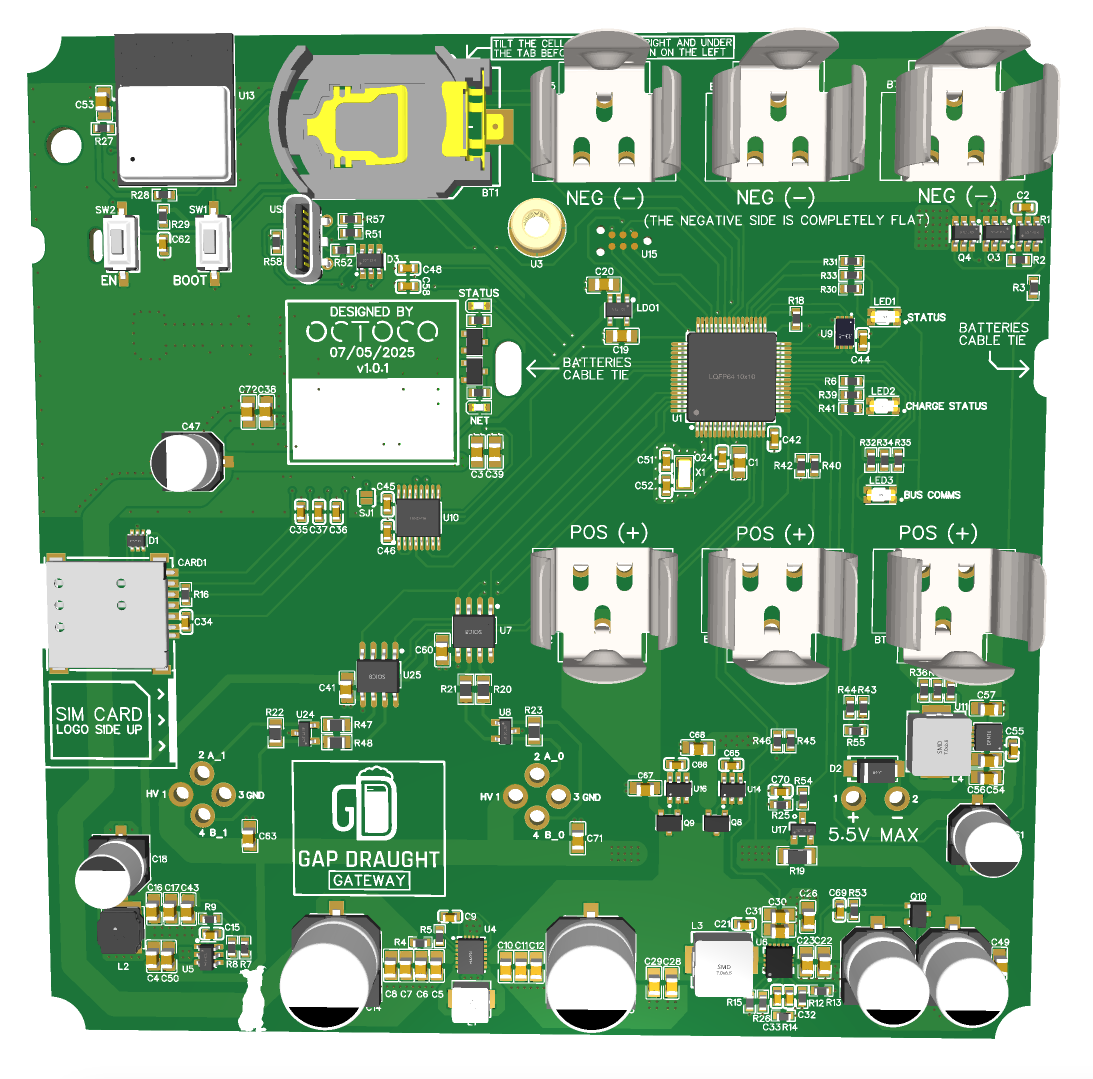
On the front of the gateway's PCB we have the following components:
- A Quectel 4G LTE modem.
- A U.FL connector for the antenna.
- Ceramic caps for decoupling.
- Matching components for the antenna's transmission line.
- A user button (not currently used).
- The footprints for the power connector and two RS485 bus connectors.
The gateway's PCB - front.
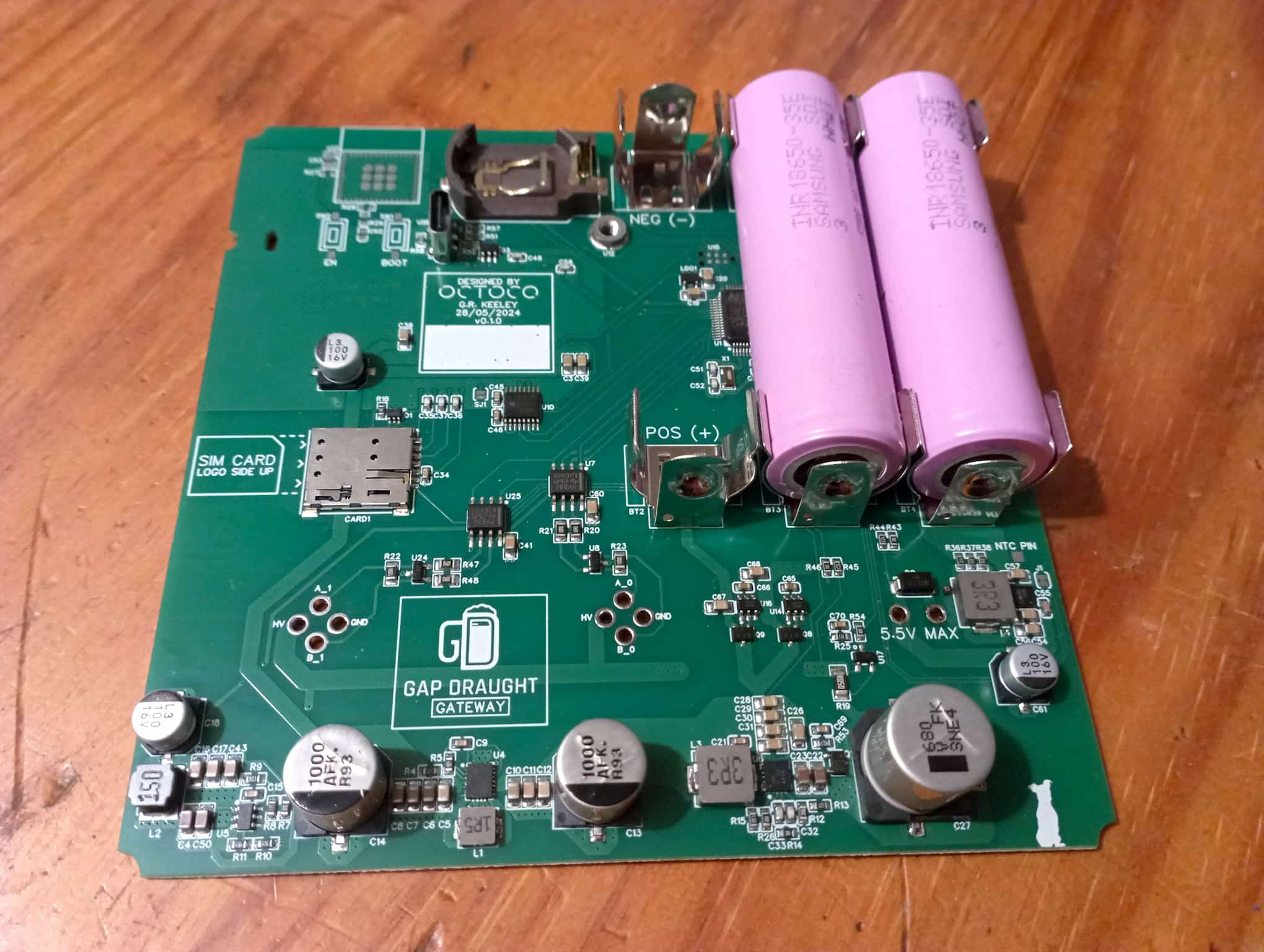
An production gateway PCB.
Node
On the back of the node's PCB we have the following components:
- An STM32G0 microcontroller.
- An RS485 driver IC and a TVS diode pair for ESD protection.
- A TVS diode to suppress voltage spikes on the bus power supply.
- Rear-firing LEDs to indicate the state of the taps and state.
- A buck mode SMPS to convert the 18V bus voltage to 5V.
- An LDO to convert 5V to 3V for the MCU and peripherals.
- Four sets of tap circuits:
- An op-amp relaxation oscillator circuit for TDS sensing.
- TVS diodes to prevent ESD damage.
- A voltage divider for the pressure sensor.
- A resistor for the NTC sensing circuit.
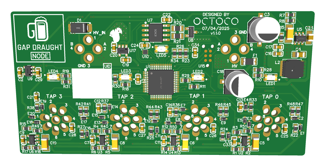
The node's PCB - back.
On the front of the node's PCB we only have the footprints for the four tap
connectors and two RS485 bus connectors.
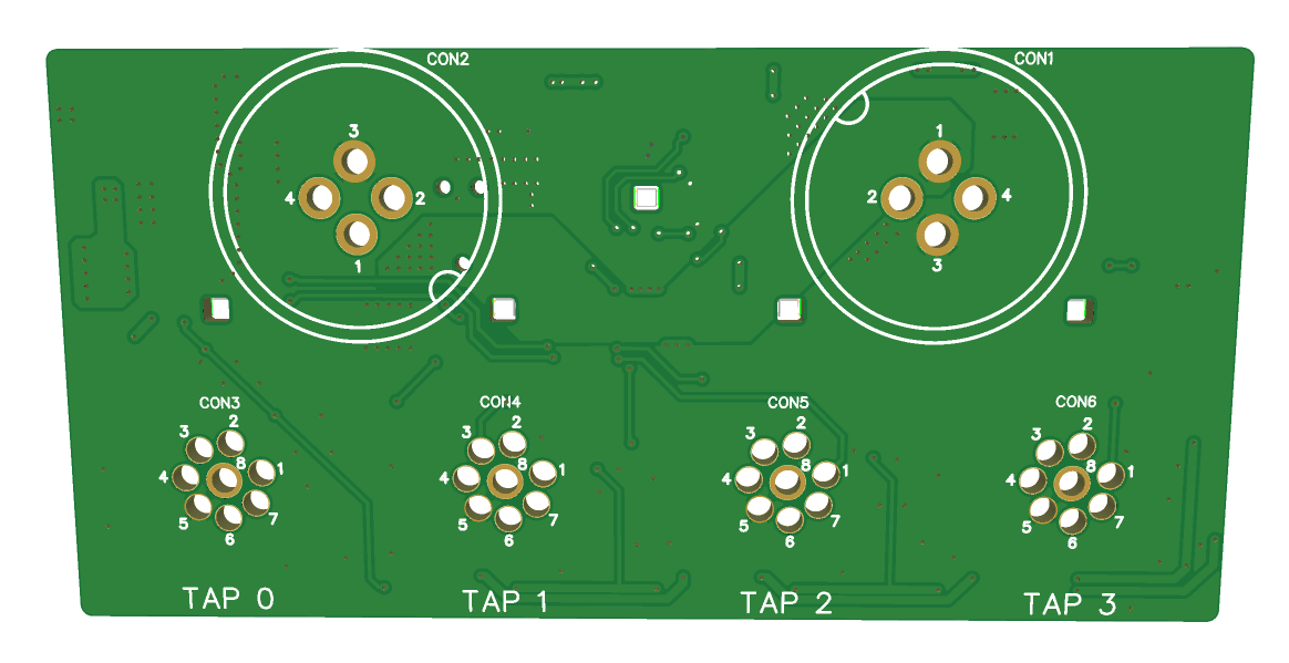
The node's PCB - front.
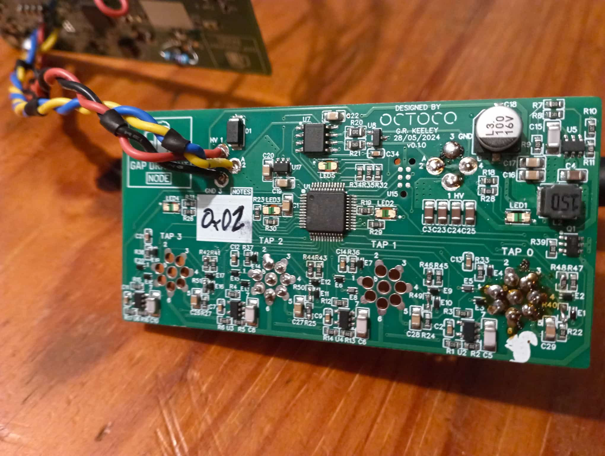
Two production Node PCBs.
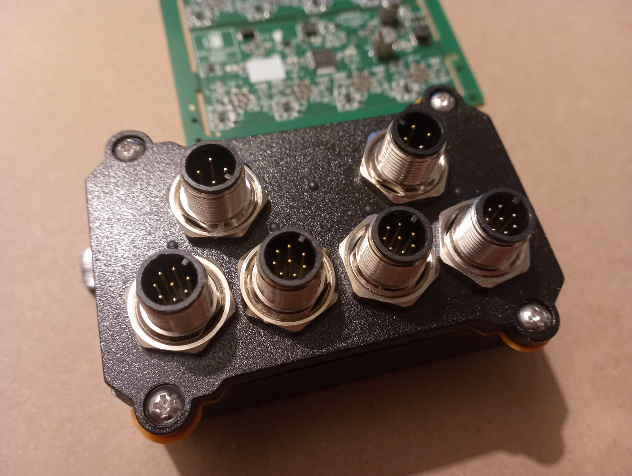
A complete Node.
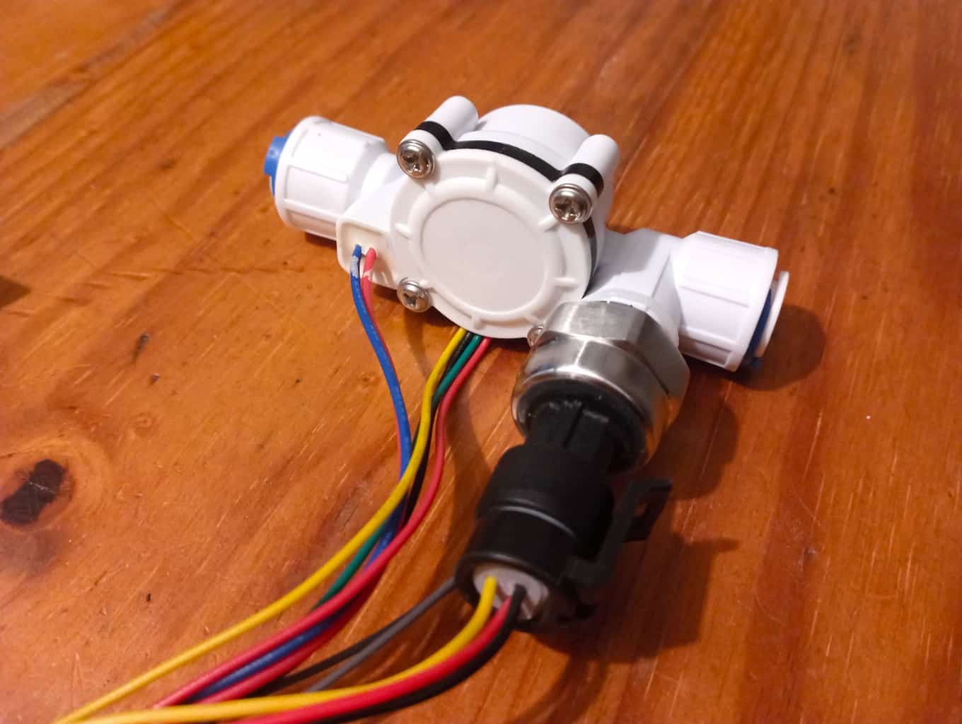
The tap sensing unit used.
Single Tap Unit
We are currently developing a single tap unit for monitoring a single tap.
This PCB will fit into a custom enclosure that will sit directly on top of the meter.
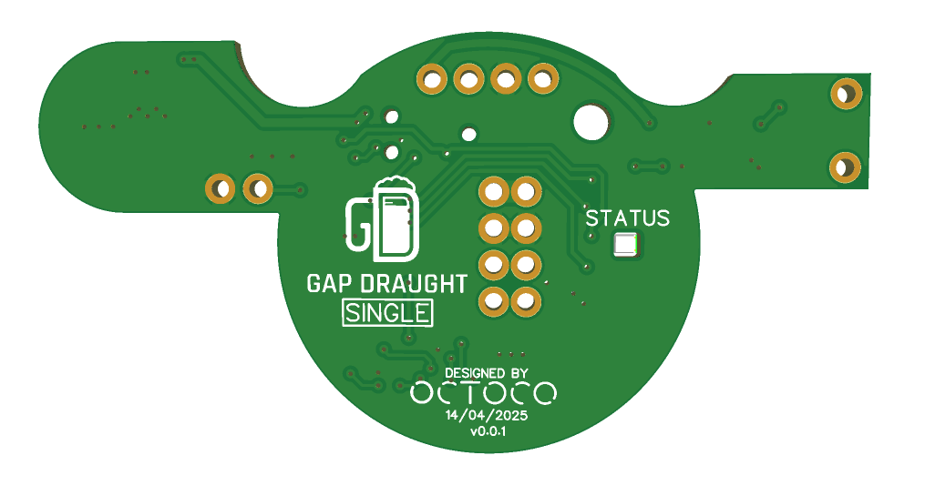
The single tap unit's PCB - front.
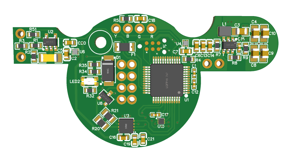
The single tap unit's PCB - back.
Testing
We were allowed to test the device in a real-world scenario at Bohemia, a local student bar.
The device was connected to one of their Black Label beer taps and the beer cooler that sits right below the tap.
The following graph shows pours from a Saturday afternoon and evening; this was during the university
holiday period, so the bar was not as busy as it would be during the semester.
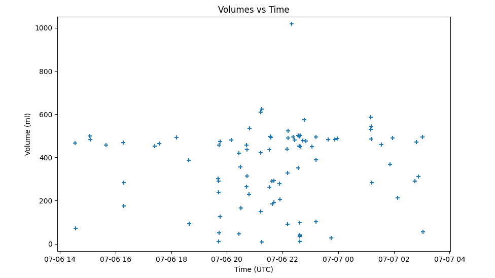
A Black Label beer tap from 14:00 in the afternoon to 03:00 in the morning.
This graph shows fairly typical 'pours' with many at or around the 500ml draught
volume and then many smaller pours (topping off or a single pour that was interrupted).
Production testing
Currently we have begun production testing in the following locations:
- Riverhead Brewery Tap in Manchester United Kingdom.
- During the Dubai Sevens rugby tournament 2024 we monitored a temporary bar setup.
- The Kingfisher Oldham in Manchester United Kingdom.
- Hawkstone Brewery - Jeremy Clarkson's brewery in Cheltenham United Kingdom.
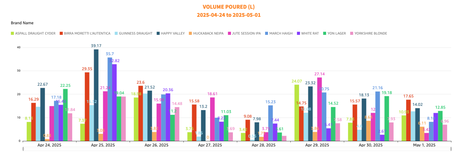
Riverhead Brewery Tap - A week of pours.