Agri Technovation's Picklogger V2
If you're not familiar with the Picklogger project, you can read more about it and its origins
here.
In that project, which we refer to as Picklogger V1.5, we took the original Picklogger and redesigned its hardware and
firmware to improve its produceability and manufacturability.
In this write-up, I'll focus on the changes made in the Picklogger V2 project. For more details,
feel free to read the Picklogger V1.5 write-up (there are also some nice photos and data to look at).
The Picklogger V2 project's focuses were two-fold:
- Drastically improve form factor (for the US market).
- Redesign and rethink the cut-detection mechanism.
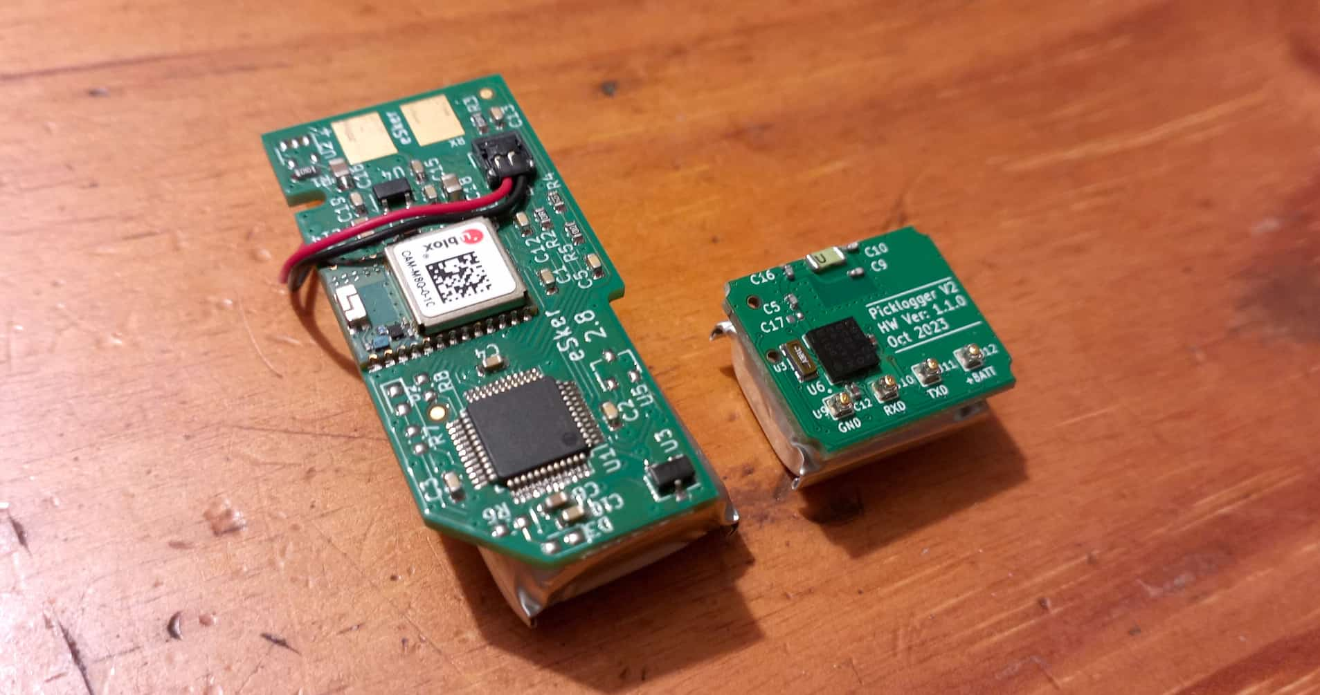
The resulting product was a PCB that was a third of the size of the original and a new cut-detection mechanism that was able
to detect cuts based purely on the accelerations of the scissors' handle during a cut.
The V1 PCB and battery next to the V2 PCB and battery.
My role in this project was to design the hardware and firmware for the new Picklogger.
The sheer size of the hardware made the component choices challenging.
I was also in close contact with the industrial designers to ensure that the hardware and enclosure were compatible.
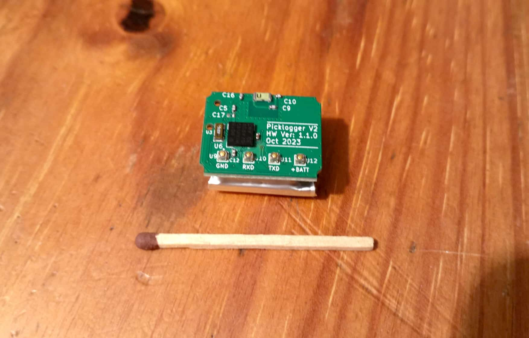
The PCB was designed on KiCad (a free and open-source PCB design software). On the front side of the PCB we have the following components and features:
- GPS module - This module allows us to know where in the world, and more specifically, where in the orchard, we are.
- GPS antenna - So that the GPS module can pick up the radio signals from space.
- Real Time Clock crystal oscillator - So that the GPS can maintain an accurate internal time (this is important for the GPS to be able to predict where in the sky the GPS satellites will be at any given time).
- Charger interface pads - Spring-loaded 'pogo' pins are soldered to these pads; these pins make contact with the enclosure's pins on assembly.
These pins are used to interface with the dock to download the cuts, charge the device and update the firmware.
A render of the front of the Picklogger PCB.
An actual Picklogger PCB and battery.
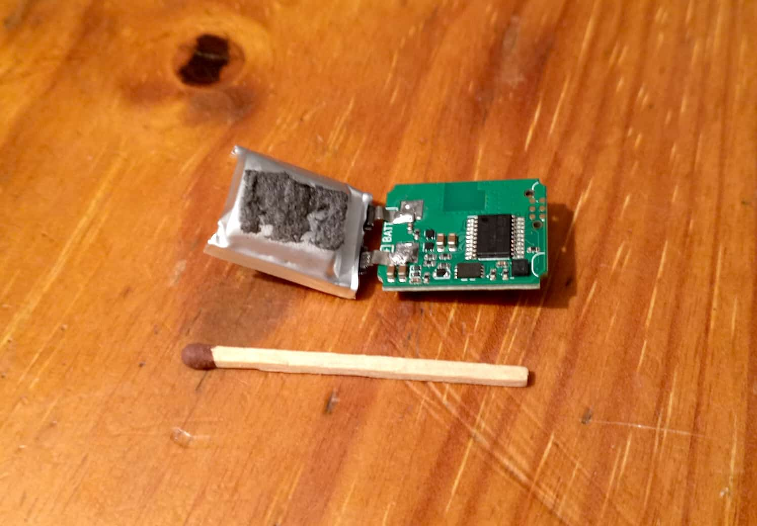
Things are a bit busier on the back side of the PCB. Many hours were spent finding components that were not only small enough and cheap enough but also readily available.
- Microcontroller - The microcontroller is responsible for all of the Picklogger's logic (such as
reading in the device's location from the GPS module and processing the acceleration
data to determine if a cut has occurred).
For those of you who don't know, a microcontroller is akin to a tiny computer.
This microcontroller only has 32KB of flash memory and 8KB of RAM.
- Flash memory - This flash chip is used to store the details of the thousands of cuts.
- Accelerometer - This component is used to detect the accelerations of the scissors' handle during a cut.
This acceleration data then goes through a signal processing algorithm to determine if a cut has occurred.
- Programming pads - During production, the device is programmed with this connector.
A render of the back of the Picklogger PCB.
The back view of an actual Picklogger PCB.
The basic functionality of the firmware is the same as the
Picklogger V1.5.
The main difference is the cut detection mechanism. Prof. Gert-Jan van Rooyen (co-founder of Ocotco)
specialises in signal processing. He was brought in to develop the cut detection algorithm.
We had to work together to ensure that the algorithm was not only accurate but also computationally efficient
due to the limited specs of the microcontroller chosen. Gert-Jan was also able
to build in 'fake cut' rejection into the algorithm to prevent the workers
from trying to falsely bulk up their numbers.
Below is a graph of the raw acceleration data captured during a data acquisition twig cut:
The raw accelerations captured during a twig cut.
The enclosure was designed by Retief Krige Industrial Design (RKID).
I was responsible for ensuring that the hardware and enclosure were compatible.
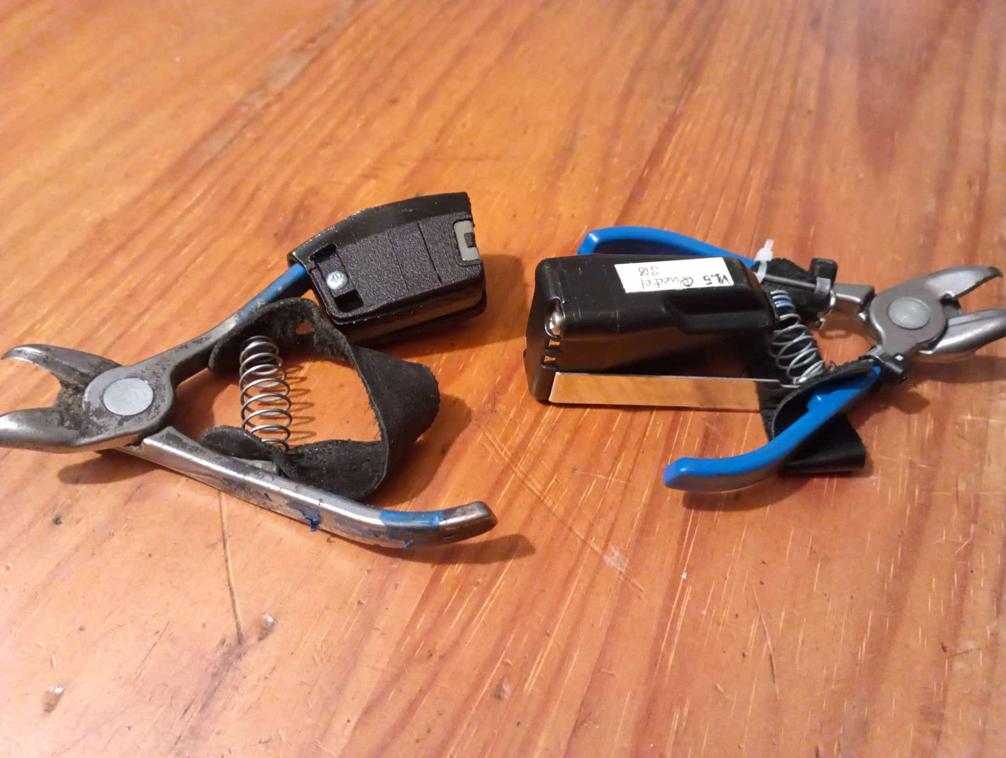
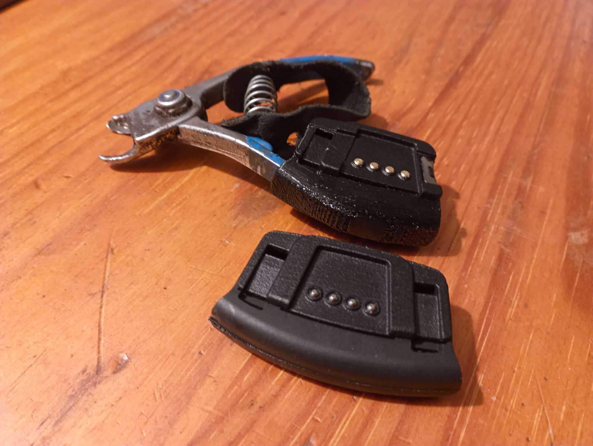
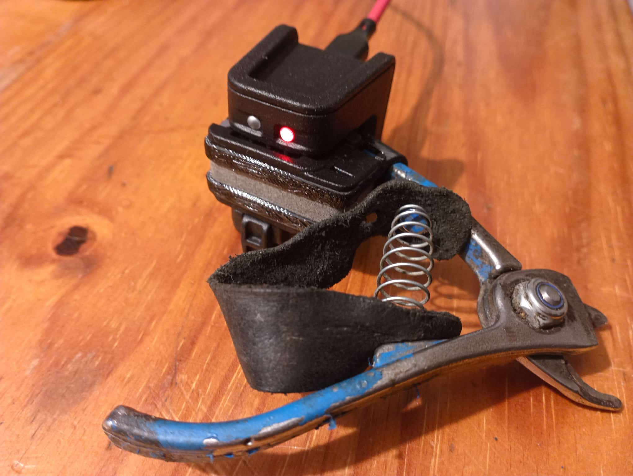
As can be seen in the image below the new design has vastly improved ergonomics:
The V2 enclosure next to the old V1 enclosure (also designed by RKID).
The newest enclosure (on the scissors) and the initial V2 design.
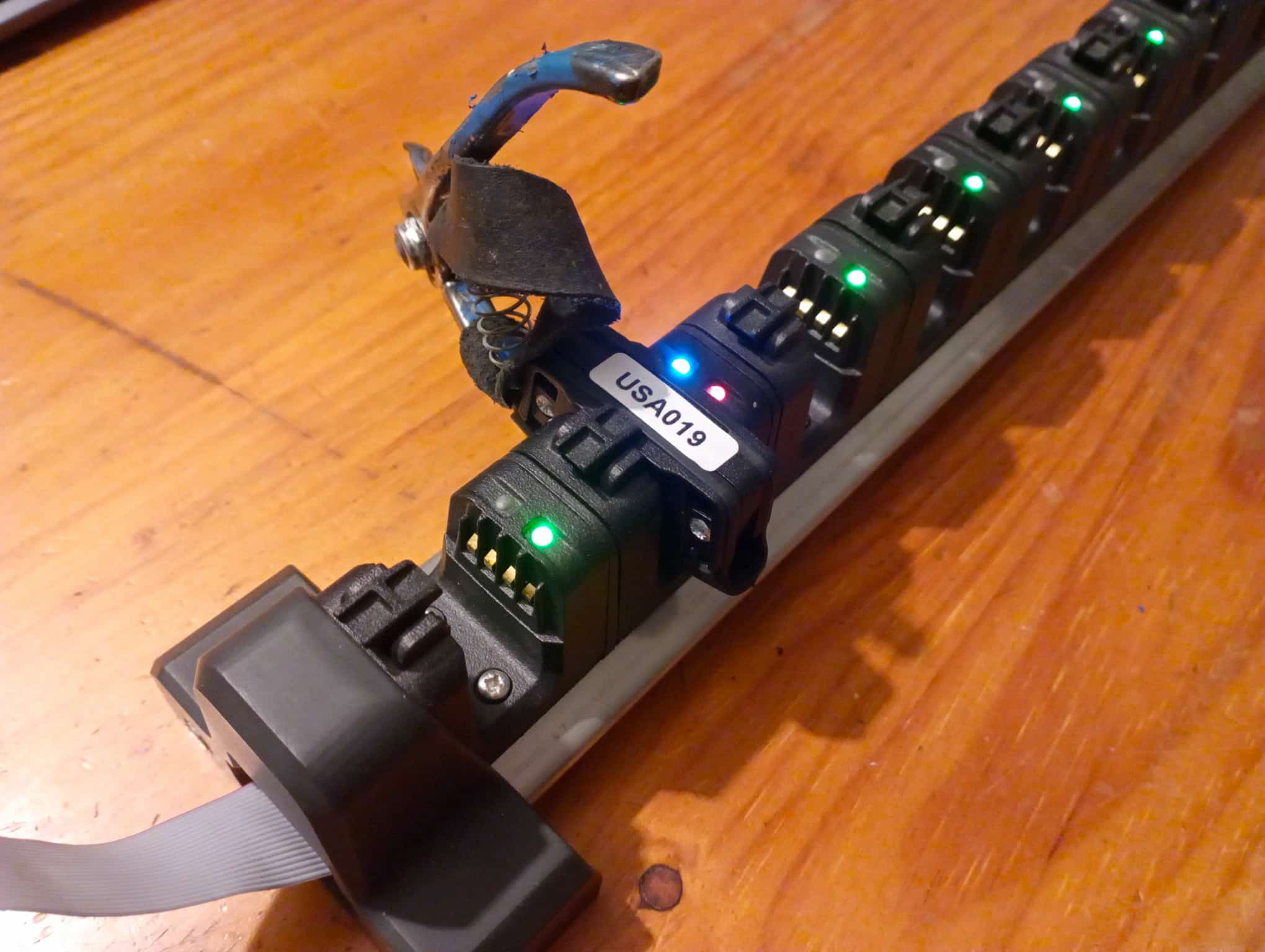
I was also tasked with developing the hardware and firmware for the docks.
The dock is responsible for charging the Picklogger and extracting and uploading the data.
The multi-dock was designed to have up to 16 slots (4, 8 and 12 slot versions are also possible due to the modular design).
A single dock is also avaliable for independent contractor pickers.
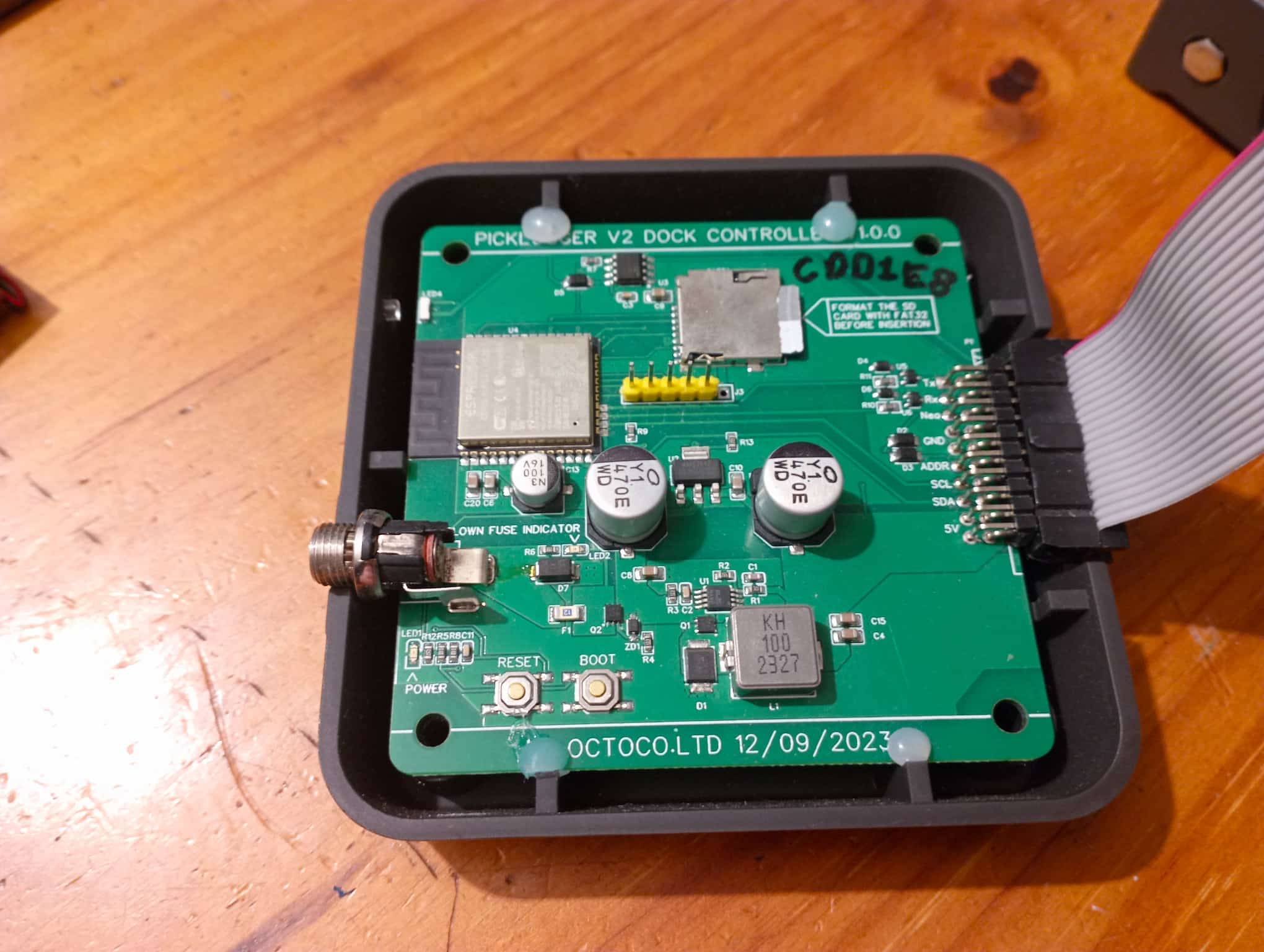
The dock's controller PCB is shown below. It communicates with the Pickloggers
via a single UART connection which is switched to specific Picklogger indices
via four I2C-controlled multiplexers. It uses an ESP32 to manage the extractions
and to upload the data to the cloud. The ESP32 doesn't process the data received
from the Pickloggers; it simply checks that the data is valid and then uploads it to
an ETL AWS lambda function. By doing this, the data uploaded by the ESP32 is 19 times
smaller than uploading JSON.
A Picklogger in a 12 position dock.
Single Dock
A single dock was also designed to connect to a PC or phone via USB-C. There is also a Bluetooth dock
available in a similar form factor.
©2026 Gavin Keeley, All Rights Reserved.

